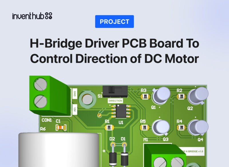
A motors driver that can control the speed and direction of the DC motor
Hardware Components:
Software Tools:
- Inventhub
- Altium Designer
What is an H-Bridge Driver?
H – Bridge driver is a standard motor driver that can control the speed of the motor and its direction either forward or backward. Basically, H- Bridge driver circuit is made up of four transistors that act as switches to spin or rotate the motor by turning them off or on.

Using a potentiometer there is an option to control the amount of current flowing to DC motors which control the speed of the motor. There is also a direction switch witch controls the current path and thus motor rotation direction. H – Bridge driver is a good tool for educational purposes or for hobbies.
Why Transistors?
In our H-Bridge circuit, we are using four transistors instead of conventional switches the reasons are:
- They can handle or manage enough current for the motors to protect them from damages. Their capability of controlling the current depends on how much current motor draws
- They act as a switch. We are using an NPN transistor that gives high output if positive voltages are applied at its base otherwise it gives low output
- Turning on transistors 1 and 4 simultaneously will rotate the motor in a forwarding direction while turning on transistors 2 and 3 will rotate the motor in the backward direction. Hence, the motor can be drive
Pulse Width Modulation (PWM):
We want to move our motor continuously in the forward and reverse direction, this can be done by increasing the speed of the DC motor. The speed of the motor can only be increased by increasing the voltages. The pulse width modulation is used to provide the variable DC voltage to the motor. In PWM we increase the width of the pulse as the names suggest. It can tell for how much time the pulse will remain ON and OFF.
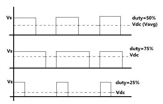
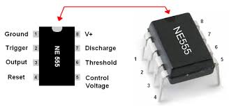
In the above figure, it is observed that for the duty cycle (a time period in which systems become active) 75% Vdc will increase to 3/4th of the supply voltages Vs, if the duty cycle is reduced to 50% then the Vdc becomes half of Vs, and if the duty cycle is decreased to 25% Vdc will also decrease to 1/4th of supply voltages. This is how PWM works for changing the speed. For PWM generation we are using an IC named NE555.
Working Description:
H- Bridge driver is a baseboard device for motors supply, controlling its direction and speed. Below is the block diagram of how it works.
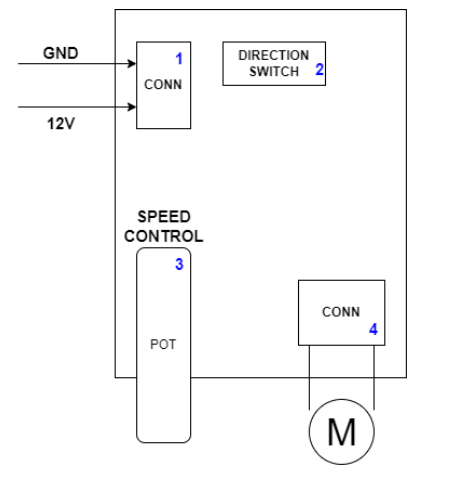
In the above diagram, you can see four main parts of the motor driver:
1- Power Supply Connector: It is to provide a board supply connector. Make sure this voltage is exactly 12V
2- Switches for the Direction: SPDT for motor direction control that will ultimately control transistors
3- Potentiometer: Potentiometer of 10kohm for current control through motor thus controls the speed of the motor
4- Motor Connector: Motor connector. Connection polarity is not important
After providing the 12V supply voltages to the circuit, the 0.1uF capacitor gets charged and the output becomes high. When a capacitor is charged to a certain threshold voltage comparator in the NE555 IC makes the output of the circuit low. Increasing the resistance the time for charging the capacitor increases hence duty cycle is increased. On the other hand, when the capacitor will get discharged the resistance value will be decreased and the duty cycle also decreased. This is how we can generate PWM and can change the speed of the motor at a certain level of threshold. Now there is a need to change the direction of the motor using the H-Bridge circuit. There is an SPDT switch next to the NE555 IC to give the PWM output to the H-Bridge circuit. Changing the position of the switch will allow us to turn on or off the transistors to change the motor direction in either forward or backward direction depending on our choice. The potentiometer can change the width or speed of the motor. This is useful for 500mA current rating for the higher current level we can use TIP1xx or MOSFETS.
I am using diodes also in my design. These diodes are for the protection of the circuit. Motors release some electrical energy and diode are used to provide a path for current to release this energy otherwise this can damage the circuit.
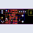
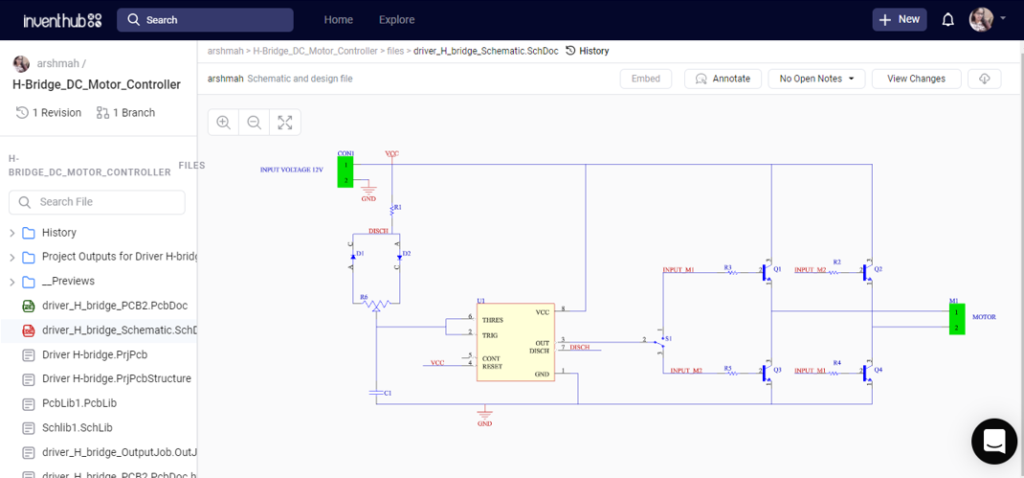
Schematic Diagram:
I have implemented my design on Altium Designer. After designing my schematic diagram I have uploaded my schematic file online on Inventhub for the users. They can view or download my design and can implement it easily without any error.
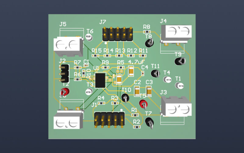
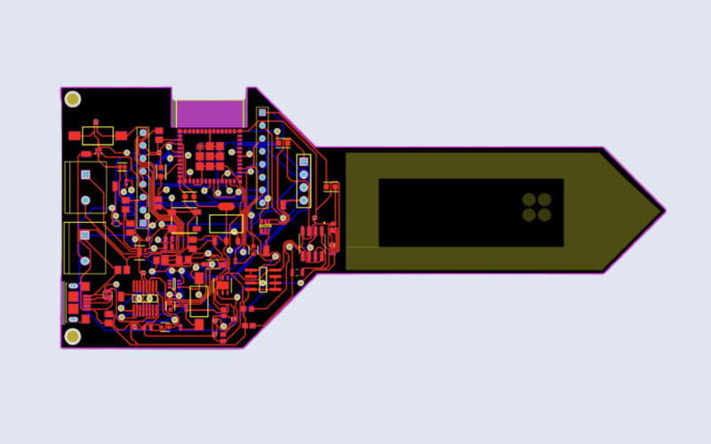
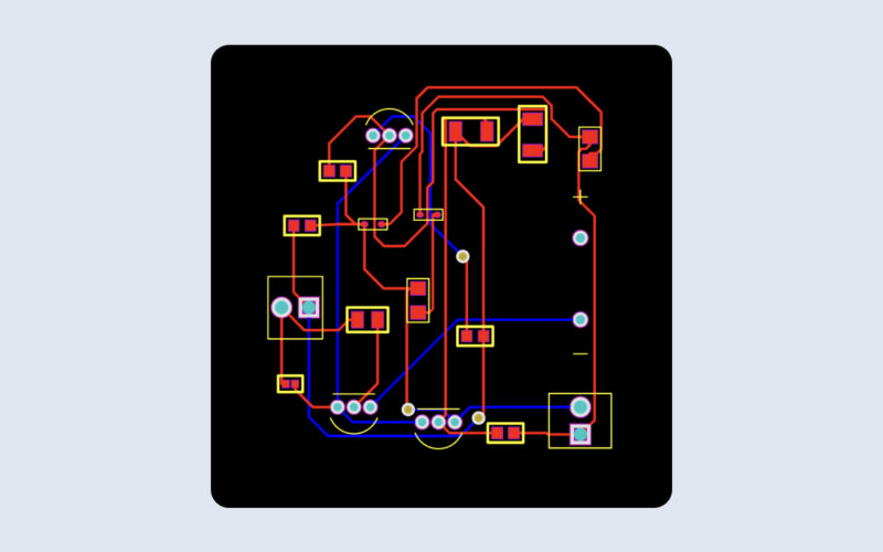
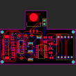
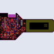
PCB Design:
For the fabrication, I have designed my PCB on the Altium after that I have made them public on Inventhub for the users and the manufacturers.
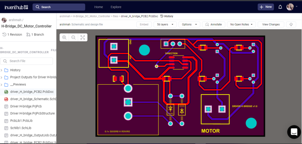
Instead of visiting the manufacturer, I can send him this file link and he can download it to fabricate my PCB with no error.
Design Files:
For those who want to view or download my design to implement it exactly, they can get my design files in ZIP file format easily. There will be no need to recreate the schematic and PCB again. Just download and use it!
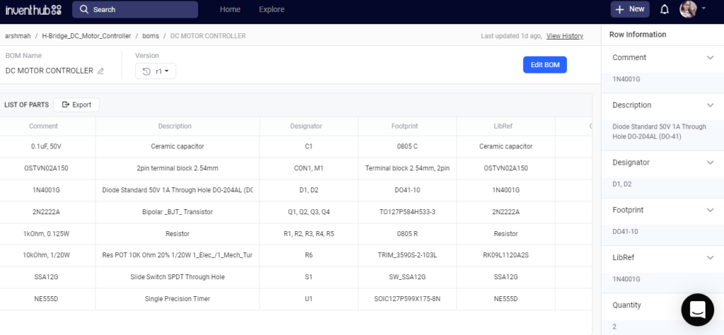
Bill of Materials:
After getting my fabricated board, I need to visit my component provider for the components of the PCB board. I have created my list of components with each and every detail of it like library reference, footprint, symbol, and quantity. This will help him in delivering the same components as I required for my design. I have uploaded my BOM file online on Inventhub from where he can view or download the details in CSV file format and can deliver my components with no waste of time.