
Plant Care is a device to monitor the health of a plant in a garden. It can measure the level of moisture in the soil, humidity level, need for water for the plant, the temperature of surroundings, etc. Using ESP32 users can also send and receive data to the server. Plant care is useful for those who want to keep an eye on the health of every single plant without going into the garden. Plant care is the ultimate solution to keep the plants healthy and fresh in gardens, nurseries, offices, and homes.
Hardware Components:
| 1. | USB TP | x1 |
| 2. | USB-SERIAL IC | x1 |
| 3. | TACTILE SWITCH | x1 |
| 4. | RED LED SMD | x2 |
| 5. | SHT20 | x1 |
| 6. | USB | x1 |
| 7. | Test point | x5 |
| 8. | Resistor 2.4k | x1 |
| 9. | Resistor 2.2K | x1 |
| 10. | Resistor 10k | x4 |
| 11. | Resistor 4.7K | x2 |
| 12. | Resistor 1M | x1 |
| 13. | Resistor 1K | x2 |
| 14. | Resistor 0 OHM | x3 |
| 15. | NE555DR | x1 |
| 16. | Resistor 1.5k | x1 |
| 17. | Resistor 100 | x1 |
| 18. | MOSFET | x1 |
| 19. | LM358DR2G | x1 |
| 20. | Ipp Tvs Diode | x1 |
| 21. | Header 8 | x2 |
| 22. | GREEN LED | x1 |
| 23. | DNF RES | x1 |
| 24. | DRV8837 | x1 |
| 25. | ESP32 | x1 |
| 26. | Capacitor 4.7uf | x1 |
| 27. | Connector Terminal 2 | x2 |
| 28. | Capacitor 1uF | x1 |
| 29. | ADJUSTABLE LED SMD | x1 |
| 30. | Capacitor 100nf | x10 |
| 31. | BJT TRANSISTOR | x2 |
| 32. | 1N5819 | x1 |
| 33. | AMS1117-3.3 | x1 |
| 34. | 1N4148WT | x1 |
| 35.. | Capacitor 470pF | x1 |
| 36. | Capacitor 10uF | x1 |
| 37. | Capacitor 10nF | x1 |
Software Tools:
- Inventhub
- Altium
- Arduino
Major Components:
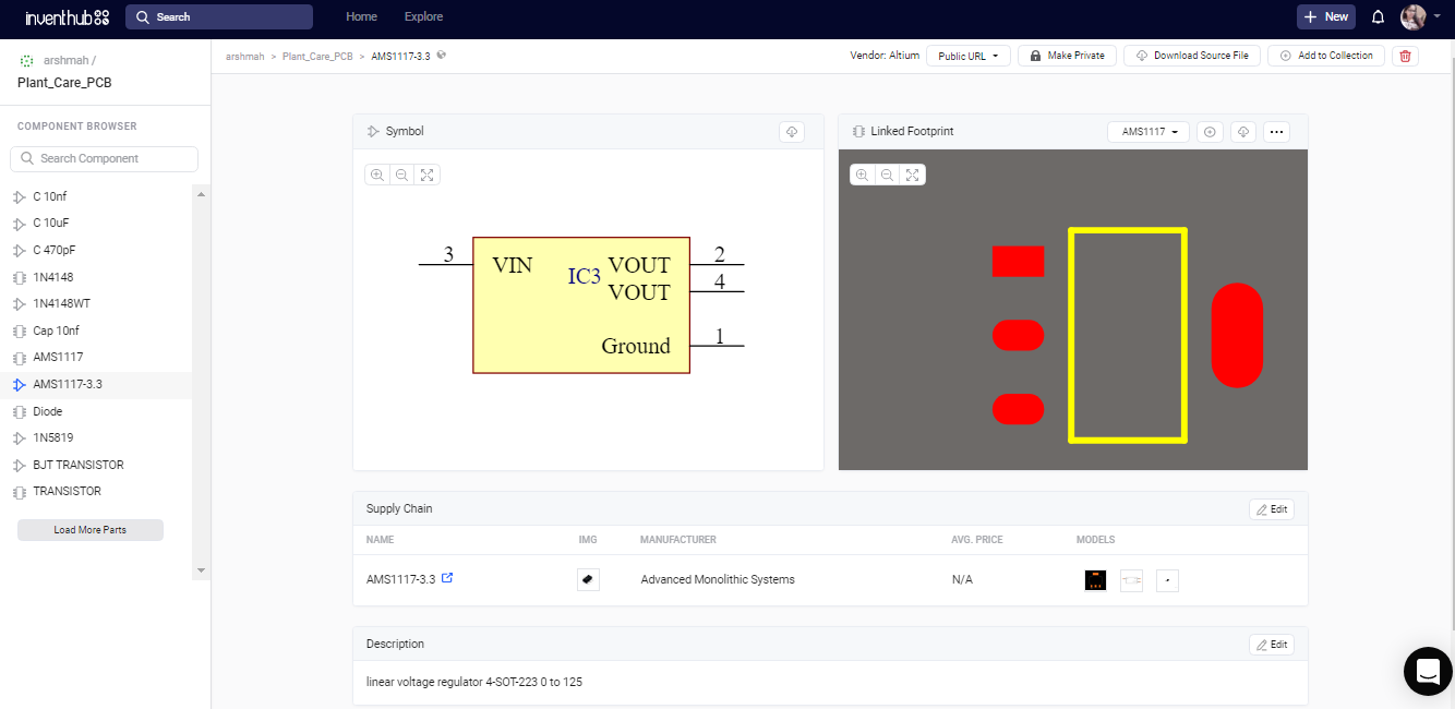
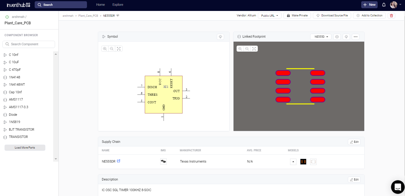
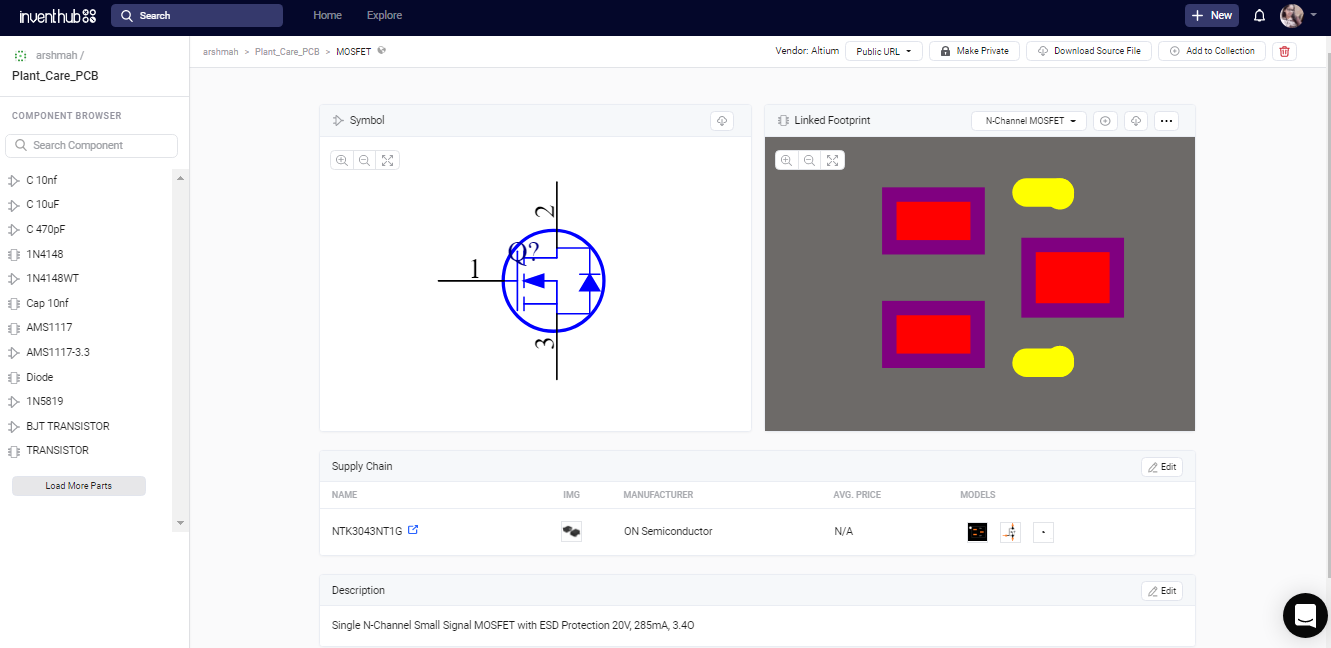
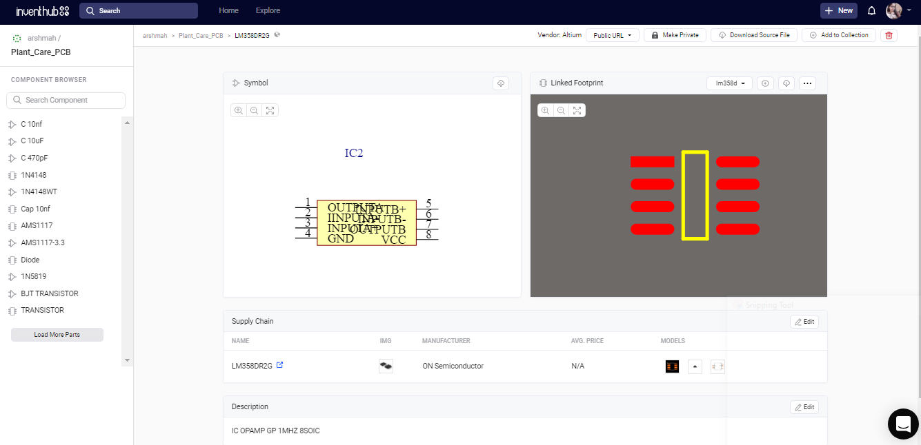
Following are the major components used in my design. I have uploaded their symbols and footprints online on Inventhub in the components management library for the users who want to implement my design. They can simply download and reuse components instead of designing them again.
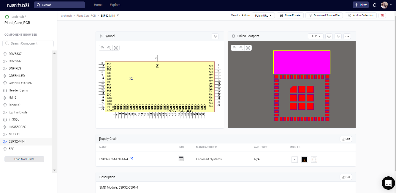
- ESP32-WROOM Module:
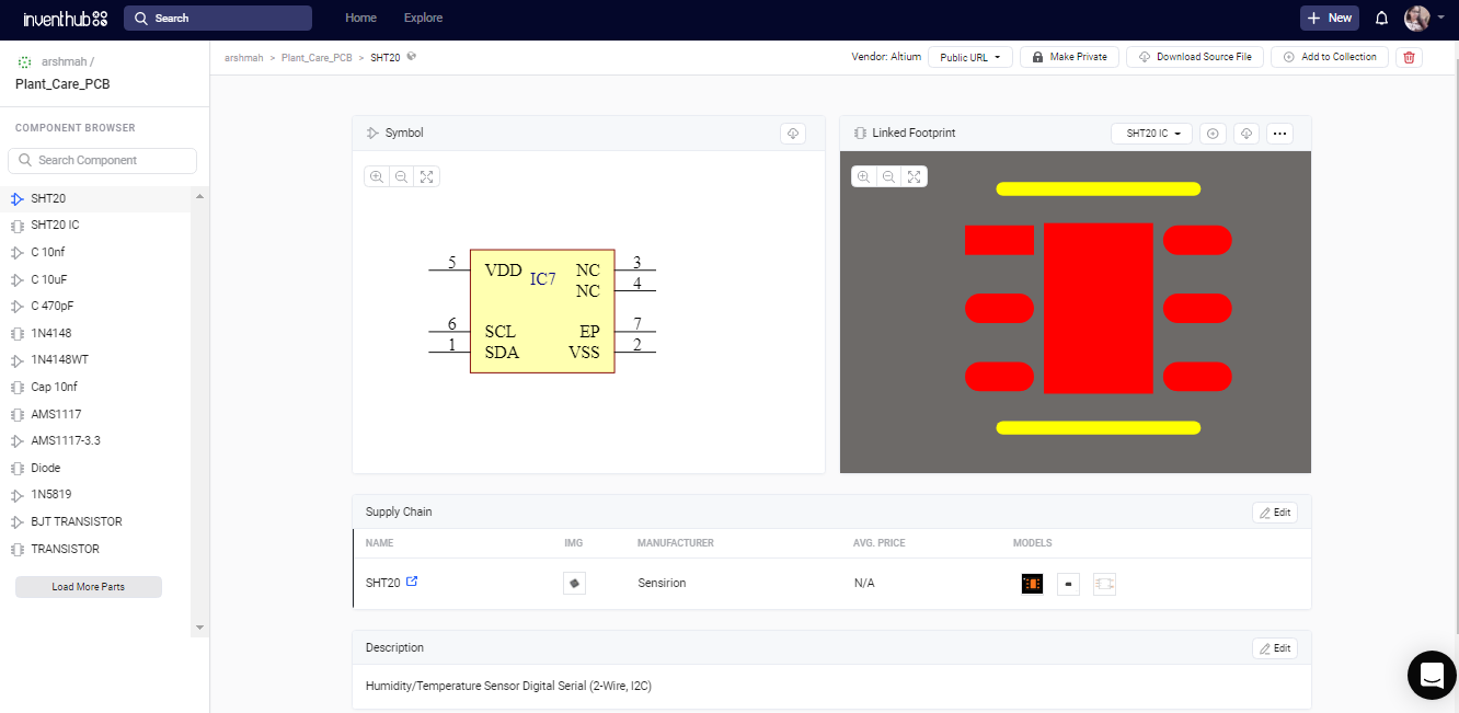
- SHT20 Sensor IC:
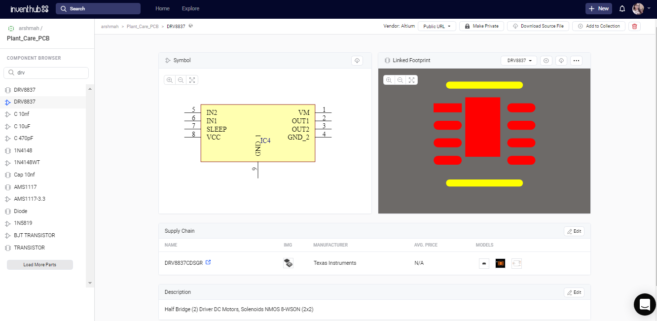
- DRV8837 Motor Driver IC:
- AMS1117 Voltage Regulator:
- USB-UART IC:

- NE555 Timer IC:
- MOSFET:
- OP AMP LM358D IC:
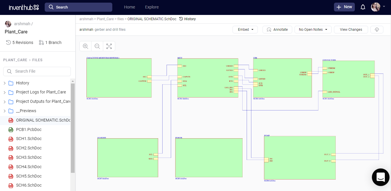
Schematic:
The main schematic file consists of a hierarchical design. I have created 7 sub-schematics that are linked to the main schematic file. While working with a complicated design it’s always a good practice to make a hierarchical design. After creating my schematic in Altium, I have uploaded all my design files online on Inventhub for the users and the manufacturers.
Design for Manufacturing:
I have converted my schematic file to the PCB file in Altium, I have uploaded my PCB file on Inventhub, where I can view my boards in different layers and can focus on a specific layer by disabling the other layers. Users and manufacturers can easily view or download my design for implementation.
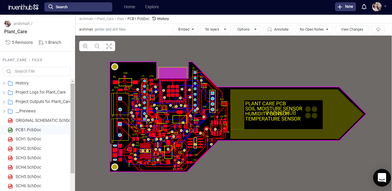
For fabrication, I have created a release file of the project on Inventhub which contains all the design files in a ZIP file format. I do not need to visit the manufacturer instead I can send him the release file of the project. He can easily download the files and can fabricate my PCB board.
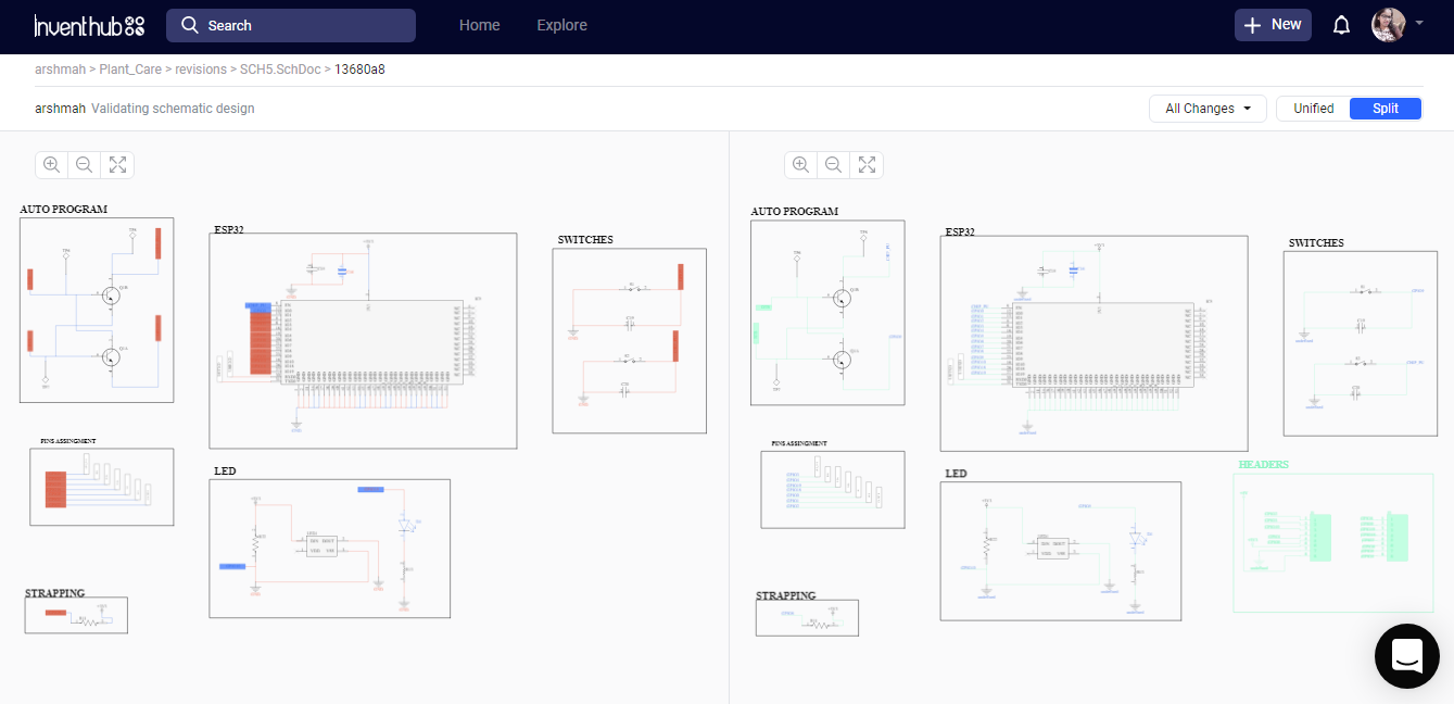
Project History:
To create a backup of my design, I have uploaded different revisions of my design on Inventhub. This contains the changes in my design at different stages. If I want to get back the specific change I have made in my design, I can go to the revision and can select that particular file, and can download it to reuse it as my current design.
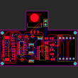
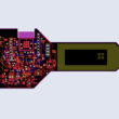
In the below figure, I have split my design into before or after making some changes; on the left side there isn’t any block of headers but on the right side block I have added headers. Moreover, on the right side, I can see some errors with the red color on the other hand right side has no errors. This will help me in comparing my design edits and I can easily decide which file I have to use for my design.
BOM file:
After the fabrication of the board, I created a list of components on Inventhub which contains the details of the manufacturer, supplier, manufacturer part number, pricing, and quantity. By just putting these details in the BOM file on Inventhub, I can easily calculate the total cost of my project automatically using the supply chain option. I can also view the datasheet of the component and can view its 3D model. Instead of visiting the component provider, I can send him this BOM file, he can download it in CSV file format and can deliver my components as per my design requirements.
To get complete how-to and detailed information on the project design and implementation visit this link: