Hardware Components:
| 1. | Red LED | x2 |
| 2. | Resistor 820R ohm | x1 |
| 3. | Resistor 33k ohm | x2 |
| 4. | Resistor 270R ohm | x1 |
| 5. | Resistor 1M ohm | x1 |
| 6. | Header 2 pins | x2 |
| 7. | Buzzer | x1 |
| 8. | Capacitor 0.1uF | x2 |
| 9. | BC547 | x3 |
| 10. | Diode 1N4148WT | x2 |
Software Tools:
- Inventhub
- Altium Designer
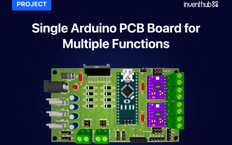
It is always a good practice to verify continuity in a circuit before implementing it. A continuity testing device is used to check the breakage and shortage of wires in a circuit. Sometimes in a complex circuit design, we are unaware of the fault so we have to test the circuit at every point to find the real problem. This plays an important role in designing the electric circuit. Here is a PCB device with a compact size board and components on it that can check the continuity as well as the polarity of the components like diodes, Zener diodes, LEDs, etc. It is important to place the components in the right polarities otherwise placing the components in opposite polarities can damage the whole circuitry. You can carry it easily in your pocket and can test your circuit anywhere.
Design files:
I have implemented the design on Altium designer. I have designed symbols and footprints for each component then I uploaded my symbols and footprints libraries online on Inventhub where users can view, download, or use them. Users do not need to design the components for their design. Thus, it can save time.

After completing the design of components. I have used them in my schematic to complete my design. I have uploaded my schematic file for the users and viewers on Inventhub.

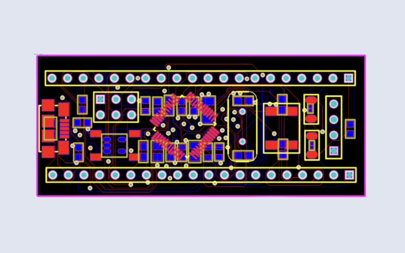
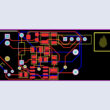
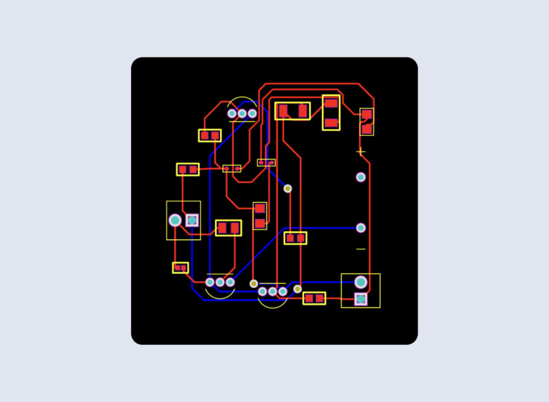
After designing schematic, I have converted my schematic file to the PCB file so that I can design a board, connect my components, and can visually view my board in 3D. I have uploaded my PCB file on Inventhub where the manufacturer can view or download my PCB file for the fabrication.

Release file:
For the manufacturer, I have created a release of my project which contains all design files including schematic, PCB, and their component libraries. Instead of visiting my manufacturer, I can send him the release of my design files. He can view or download files in ZIP format and can fabricate my PCB without any errors.
BOM file:
After getting my fabricated board, I need to embed components on it. I have created a BOM file on Inventhub which contains library reference, footprint, and quantity of each component. My component provider can simply download the file in CSV format and can send my components. I can calculate the total cost of my design by selecting the ‘supply chain’ option. I can select my distributor for the components depending on the price and availability of the components. Our total cost is $7.43.
To get complete how-to and detailed information on the project design and implementation visit this link: