An isolated synchronous buck converter that can generate multiple inverting outputs, helpful in electronics applications.
Hardware Components:
| 1. | 2200pF Capacitor | x1 |
| 2. | 10uF Capacitor | x4 |
| 3. | 2.2uF Capacitor | x2 |
| 4. | 0.01uF Capacitor | x1 |
| 5. | 0.47uF Capacitor | x1 |
| 6 | 1000pF Capacitor | x1 |
| 7. | 0.1uF Capacitor | x1 |
| 8. | 1uF Capacitor | x1 |
| 9. | 0.082uF Capacitor | x1 |
| 10. | Terminal Block 2 Pins | x3 |
| 11. | 1 pin Header | x1 |
| 12. | 0ohm Resistor | x2 |
| 13. | 2kohm Resistor | x2 |
| 14. | 127k ohm Resistor | x1 |
| 15. | 301kohm Resistor | x1 |
| 16. | 51.1kohm Resistor | x1 |
| 17. | 6.04kohm Resistor | x1 |
| 18. | 10kohm Resistor | x1 |
| 19. | Transformer | x1 |
| 20. | 5000 Test Point | x1 |
| 21. | LM5160DNTR | x1 |
Software Tools:
- Altium Designer
- Inventhub
What is a Fly-Buck Converter?
It is a simple buck converter with the addition of another winding of inductor to form a coupled inductor, a Schottky diode, and a capacitor. One side of the inductor is primary and the other side is secondary. The fly buck converter can provide an isolated voltage output which is why it is also named an isolated buck converter. This converter is useful where multiple outputs are required from a single output supply like +/- 5V, +/-9V can be created from a single fly buck converter. It is a low-power, low EMI buck converter.

Differ from other Converters:
The major thing that differentiates fly buck converters from other converters is isolation. The electrical isolation between the input and output sources. Isolation helps in reducing power noise. For safety of electronic devices in different operations, we need isolation. This converter protects the devices from damage at the input and output sides.
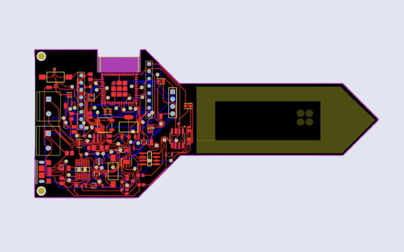
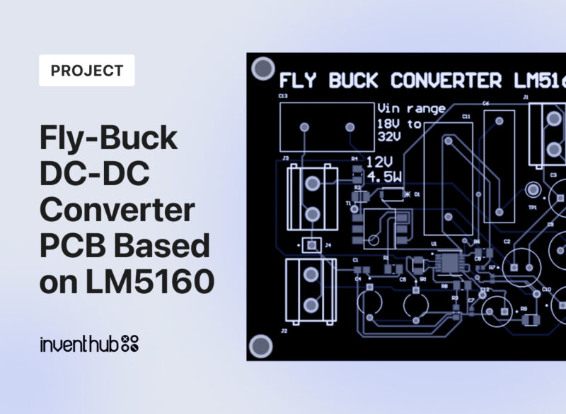
Schematic and PCB:
For the schematic diagram, I have used Altium software. I have designed symbols and footprints for each component then I uploaded my symbols and footprints libraries online on Inventhub where users can view them, download them, or use them in their design implementation. I have uploaded my schematic file for the users and viewers on Inventhub.
For fabrication of PCB, I have converted my schematic file to the PCB file. I have uploaded my PCB file on Inventhub where the manufacturer can view or download my PCB file and can fabricate my board.
Project files:
On Inventhub, I have created the backup of my design files. I have uploaded different revisions of my design files online on Inventhub, where I can view or download the specific version of my design file. If I want to use my previous design as my current design I can easily download that particular file.
For the manufacturer, I have created a release of my project which contains all design files including schematic, PCB, and their component libraries. Instead of visiting my manufacturer, I can send him the release of my design files. He can view or download files in ZIP format and can fabricate my PCB without any errors.
BOM file:
After getting my fabricated board, I need to embed components on it. Components should be of the same dimensions as I have used in my design. I have created a BOM file on Inventhub which contains a description, library reference, footprint, and quantity of each component. My component provider can simply download the file in CSV format and can deliver my components.
Specifications:
The fly buck converter provides:
- Isolation from the primary side to the output side
- Multiple isolated output voltages
- Control multiple output voltages with a single control
- Wide range of input voltages
- Low power and low EMI
- Efficiency is high
To get complete how-to and detailed information on the project design and implementation visit this link: