It is a digital contact temperature sensor with a single wire interface.
Hardware Components:
Software Tools:
- Inventhub
- Altium Designer
IC MAX30207:
It is a low-power and high-accuracy digital temperature sensor. Its accuracy to measure temperature is ±0.1°C accuracy from +30°C to +50°C and ±0.3°C from 0°C to +70°C. It has a low thermal mass (the ability to store and release heat) and can be mounted on a flex PCB with only two conducting traces, allowing for minimal thermal conduction to the system PCB and accurate temperature measurements.

Why MAX30207 is Preferred?
MAX30207 is useful for different advanced applications like:
- Wearable Body Temperature Monitoring
- Thermometers in the Medical field
- Smart Sensors (IoT based)
There are some common reasons which make it better than other temperature sensors to use:
- The accuracy and precision is high and better than others
- The size is compact that’s why used in wearable applications
- Operating voltage is from 1.7V to 3.6V
- The operating current during measurement is 67μA
- Simple and Robust Digital Interface i.e. single Wire Interface that has only one port for communication to reduce the number of components and make it simple
- Cyclic Redundancy Check (CRC) to detect accidental changes and errors in happens in digital sensors or systems
- Multidrop Capability ( a computer bus in which all components are attached to the electrical circuit like USB with a data rate speed of 12Mbits/sec)
Block Diagram:
Below is the simplified block diagram of how this MAX30207 generally works:

Working Description:
The device’s core functionality is its direct-to-digital temperature sensor. The device powers up in a low-power standby state. There are two ways to initiate a temperature measurement. The 1-Wire bus master can issue a Convert command or configure GPIO1 as a rising edge activated start conversion input, which allows temperature conversions to be triggered by an external signal. After the conversion, the resulting temperature sensor data is stored in the FIFO memory as a 2-byte temperature word and the device returns to the standby state. It is possible to sample up to 40Hz when accounting for startup time, integration time, and 1-Wire communications per sample. A sampling at high rates can lead to self-heating that may be noticeable. The output temperature data is calibrated in degrees Celsius.
After the device performs a temperature conversion, the temperature value is compared with the user-defined two’s complement alarm trigger values stored in the 2-byte Alarm High and 2-byte Alarm Low registers. The alarm high threshold, AH, is programmed in one register and the alarm low threshold, AL, is programmed in another register. If the measured temperature is lower than AL or higher than AH, an alarm condition exists and the corresponding status bit is set in the STATUS register. All devices with a set alarm flag respond to the command, allowing the master to determine which devices have experienced an alarm condition. If the alarm settings change while the device is under an alarm condition, the alarm status must be cleared and another temperature conversion executed to update the alarm condition.
Schematic Diagram:
I have designed this PCB on Altium. For the schematic, I have created two files one for flex PCB and the other for the MAX30207 interface. After designing, I have uploaded them on Inventhub for the users who want to implement my design they can view or download it from Inventhub.
MAX30207 Flex:
On the flex PCB schematic, there is a 6 pin connector, a capacitor, and a MAX30207 temperature sensor.

MAX30207 Interface:
On the PCB board, there are some test points, some headers, and connectors, and a single wire channel DS2484R+T IC for the I2C communication.

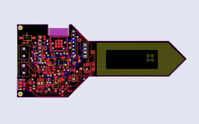
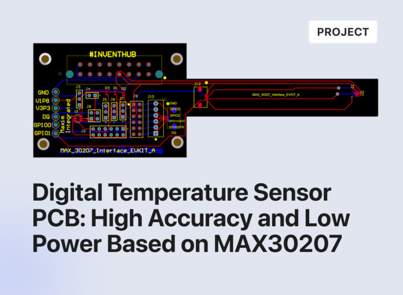
PCB file:
After designing the schematic, I have converted both my schematic file to a single PCB file in which I have combined a flex PCB with the Interface PCB board of MAX30270. Then I have uploaded the design files online on Inventhub for the manufacturer and the users.

Design for Manufacturing (DFM):
For fabrication, it is important to have the availability of design files. After completing my design I have created a release file of my project on Inventhub which contains the schematic, PCB and library files in a ZIP folder. Instead of visiting the manufacturer, I can send him this file he can view or download it and can fabricate my PCB board without any error.

Project History:
To create a backup of my design files, I have uploaded different revisions of my design on Inventhub. This contains the addition or removal of components in design at different stages. If I want to get back the specific change I have made in my design, I can go to the revisions and can select that particular file and can download it to reuse it as my current design.

Bill of Material:
I have created a detailed list of my components in BOM section on Inventhub which contains the component’s name, library, footprint, description, manufacturer and quantity. My component provider can get my BOM file in CSV file format and can deliver my component as per my design requirements without any error. I can also calculate the total cost of my design by clicking on ‘supply chain’ button.

3D view: