Hardware Components:
| 1. | Voltage Regulator | x1 |
| 2. | Rotary Encoder | x1 |
| 3. | Resistor 665 ohm | x2 |
| 4. | USB Connector | x1 |
| 5. | Resistor 10k ohm | x2 |
| 6. | Resistor 100k ohm | x2 |
| 7. | Resistor 4.75k ohm | x2 |
| 8. | Resistor 50 ohm | x3 |
| 9. | Connector header 4 pins | x1 |
| 10. | MCP6002T | x1 |
| 11. | Connector 14 pins | x1 |
| 12. | Conn Header 20 pins | x1 |
| 13. | Capacitor 10nF | x3 |
| 14. | Capacitor 1uF | x1 |
| 15. | Capacitor 100 nF | x2 |
| 16. | BNC Connector | x1 |
| 17. | Arduino pro mini | x1 |
| 18. | 1N4148WT | x2 |
Software Tools:
- Altium
- Inventhub
What are Antennas? How do they work?
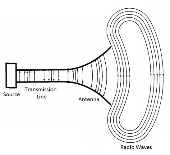
Antennas are everywhere! An Antenna is an electrical device that converts electric power into electromagnetic waves or radio waves and vice-versa. In every wireless communication, antennas are involved. Antennas can transfer signals fatly and easily.
How do they work? The antennas can be used for both transmission and reception of electromagnetic waves. The transmitting side of the antenna collects electrical signals from a transmission line and converts them into radio waves whereas the receiving side of the antenna accepts radio waves from the space and converts them to electrical signals and gives them to a transmission line.
Parameters of Antenna:
- Voltage Standing wave ratio (VSWR)
- Noise
- Input Impedance
- Polarization
- Gain and Efficiency
- Pattern of radiation
Introduction to Antenna Analyser:
An antenna analyzer is a radio frequency analyzer used for determining the performance of antenna systems in radio electronics applications. It is a signal generator that sends a signal to the attached load and a readout that displays a set of results. It measures the impedance matching of the electrical circuits made up of the transmitter or the receiver, RF feeder, and antenna. Impedance matching determines how much energy from the transmitter reaches the antenna and how much of the RF signal received by the antenna actually reaches the receiver.
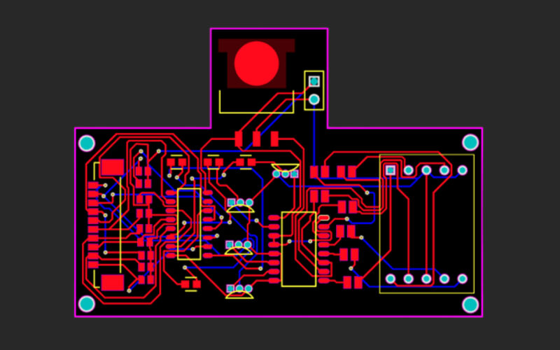
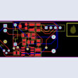
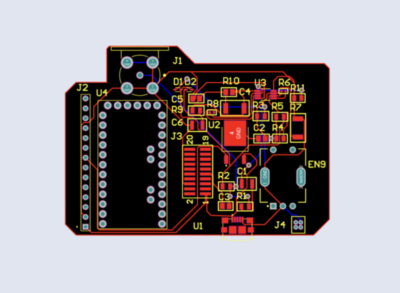
PCB Circuitry:
It is a 0-40MHz amateur radio antenna analyzer. A pocket device that measures the parameters of the antenna easily. We can add LCD to display graphically the results of the analysis.
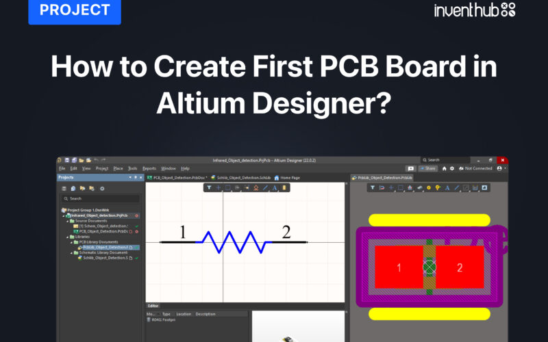
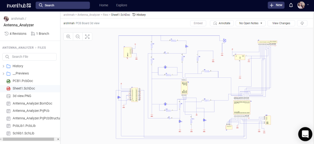
I have used the Altium designer to design my schematic diagram. I have uploaded my schematic file online on Inventhub for the users who want to implement my design. They can go to the provided link and can view or download my design easily. I can also view the changes I have made in my design by going to the ‘view changes’ tab. I can also collaborate with the people, they can comment on my design and can give suggestions to improve my design further.
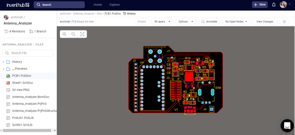
I have converted my schematic file to the PCB file in Altium, where I can create connections on the board, define the shape of the board, arrange the components on the board, and can view my PCB in 3D view. I have uploaded my PCB file on Inventhub, where I can view my boards in different layers and can focus on a specific layer by disabling the other layers. Users and manufacturers can easily view or download my design for the implementation.
Design for Manufacturing:
I have created a release file of the project on Inventhub which contains all the design files in a ZIP file format. For the fabrication, I do not need to visit the manufacturer instead I can send him the release file of the project. He can easily download the files and can fabricate my PCB board.
Revisions:
To create a backup of my design, I have uploaded different revisions of my design on Inventhub. This contains the changes in my design at different stages. If I want to get back the specific change I have made in my design, I can go to the revision and can select that particular file and can download it to reuse it as my current design.
Bill of Materials:
After the fabrication of the board, I created a list of components on Inventhub which contains the details of the manufacturer, supplier, manufacturer part number, pricing, and quantity. By just putting these details in the BOM file on Inventhub, I can easily calculate the total cost of my project automatically using the supply chain option. I can also view the datasheet of the component and can view its 3D model. Instead of visiting the component provider, I can send him this BOM file, he can download it in CSV file format and can deliver my components as per my design requirements.
To get complete how-to and detailed information on the project design and implementation visit this link: