LifePO4 USB charger is a simple device that operates as a LifePO4 cells charger. As a power source for a charge, the device can be connected to a solar panel or USB cable.

Hardware Components:
Software Tools:
- Inventhub
- Altium Designer
Background Story:
A lot of electronics systems and developer boards use batteries as power supplies. The problem is that the battery becomes empty after some period of device operation?
On the other hand, some robotics-related projects can use batteries as the main power source.
Let’s use an RF-controlled toy car as an example. Toy cars have 2 DC motors that are controlled with the main MCU and they are connected to 2 wheels. Toy cars can’t have a big battery because of their limited dimensions. Main MCU receives data from remote controller via RF communication and received data represents duty cycle for PWM which controls the speed of DC motors and thus the direction of the car. DC motor is an actuator that consumes a lot of current directly from the battery, plus logic which is also powered by a battery. If a toy car uses a LifePO4 cell with 600mAh capacity, and 2 DC motors consume 250mA per motor, then the full battery will get drained in about an hour. So, you have to charge your battery every hour, but you need it to be quick because you want to proceed with toy car testing.
Let’s imagine a device that is simple LifePO4 cells USB charger. Connect your LifePO4 battery to the developer board (Arduino, RPi, ESP32) and connect the LifePO4 USB charger. Your system will probably never get drained because you have a constant power supply that charges the battery. For toy cars, get 2 same batteries and charge them to maximum capacity. When first get drained, place it in the LifePO4 USB charger and use another cell for toy car testing. The first battery will get charged before the second gets drained! LifePO4 USB charger is in basic MPPT tracker which can easily sustain solar panel up to 16V open-circuit voltage at LifePO4 USB charger input.
Working Description:
LifePO4 USB charger is a various use device. As previously explained it can be used in different modes of operation, when a power source is provided. The main goal of the LifePO4 USB charger is to provide the constant voltage at battery output:

USB micro-B:
USB micro-B connector. Connect the USB cable to this connector with a micro-B plug. MPPT is capable of up to 4A charging current. Make sure you use the correct USB cable.
MPPT device:
A maximum power point tracking device is used to provide constant voltage at outputs BAT+ and BAT-. The MPPT device can be powered with USB micro-B or two pads for solar panel wire soldering. Don’t power device with both (USB micro-B and solar panel) at the same time. It provides a maximum input voltage of 16V and a maximum power point tracking voltage of 4.6V. The output voltages of the MPPT device are usually 3.625V and a full-scale charge current is 1.4A.
LED:
RED LED is used for the charging indicator. When the battery start’s charging, the LED turns on, and when the charge is finished, the LED turns itself off.
Segment for selecting D- output pin:
Selection is done using two pins male headers, pitch 2.54mm. D- output can be connected to:
- D- of USB micro-B or
- MPPT pin. Voltage value that indicates present power point tracking value. For maximum power point tracking status, this voltage is equal to 1.205V
Additional output:
There is four pads output with:
- BAT+
- D-, selected from segment 4
- D+ directly from the micro-B USB connector and
- GND
Battery output:
There is two pads output with:
- BAT+
- BAT –
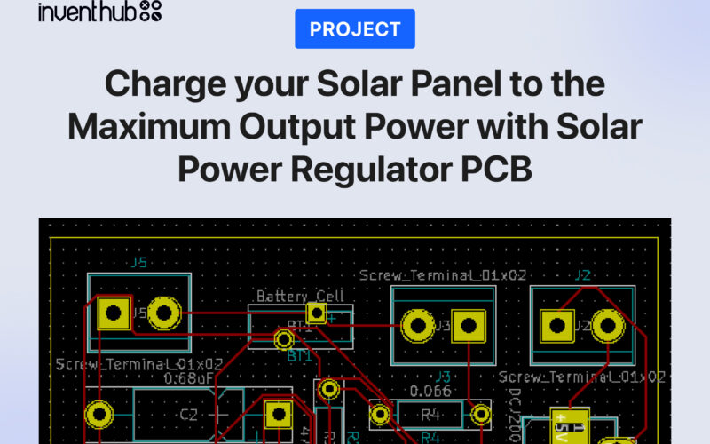
Schematic Diagram:
To design a schematic diagram, I have used a CAD software named Altium Designer. For user designing and at the time of manufacturing, it sometimes gets difficult to implement the exact design as per requirement. In order to avoid this inconvenience, I have uploaded all my design files including the schematic and PCB online on Inventhub.
Below is the link where you can find my design files.

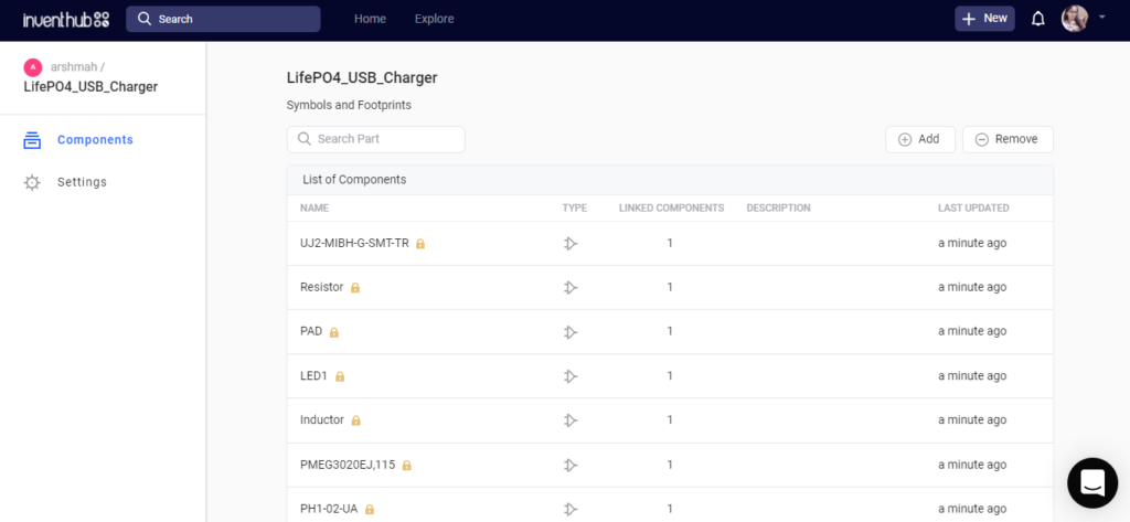
Symbols and Footprints:
Before directly jumping to the schematic design it is a good practice to design symbols and footprints of the schematic. The parameters and dimensions of the component’s symbols and footprints on software should be the same as we want them to use in reality. To get the perfection in the design, I have uploaded the symbols with their footprints on Inventhub, from where users can download them and can use them in their design.


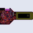
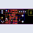
PCB Board Design:
At the time of fabrication and final implementation of the design board, it’s important to take care of routing, board and components dimensions, their symbols, and footprints.
I have created my PCB board and then I have uploaded it on Inventhub.

I can easily collaborate with people to improve my design further through annotation.

Design for Manufacturing:
I have created a Release of my project on Inventhub where my whole project is available in ZIP file format. This will help users and manufacturers to reach their exact final design.

Bill of Material (BOM):
When I will get my board fabricated, I need to embed the components on it. Instead of visiting my component provider manually and telling him the dimensions and quantity manually, I will send him my BOM file (which will be containing each and every detail of my components) uploaded on Inventhub. He will download that file in CSV format and will deliver my components.

Applications:
- It’s cheap and cells can get charged using the only USB port
- Using this device gives users the ability to charge LifePO4 cells in various projects and implementations
- LifePO4 USB charger can be used in various situations. It can be used as a direct power source for some developer boards, as direct LifePO4 charger from the USB connector, as UPS in combination with LifePO4 battery and developer board, as solar panel LifePO4 charger
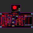
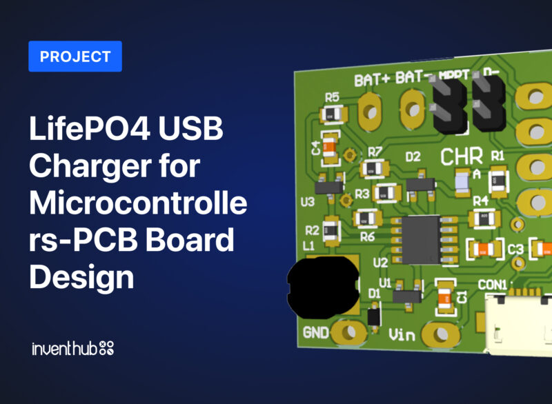
PCB 3D View:
The following pictures show 3D prints of PCB (top and bottom) and mechanical drawings in millimeters.