A power supply that converts the main AC supply to a 12V DC supply to protect the devices from damages.
Hardware Components:
| 1. | Capacitor 0.1uF/16V | x1 |
| 2. | Capacitor 470pF/50V | x1 |
| 3. | Capacitor 1500uF/25V | x1 |
| 4. | Capacitor 100uF/25V | x1 |
| 5. | Capacitor 22uF/400V | x2 |
| 6. | Capacitor 472M 2KV | x1 |
| 7. | Capacitor 100nF/16V | x1 |
| 8. | Diode P6KE200A | x1 |
| 9. | Schottky Diode SR360 | x1 |
| 10. | Bridge Rectifier IC DB107 | x1 |
| 11. | Rectifier Diode FR106 | x1 |
| 12. | Fuse 1A 250VAC | x1 |
| 13. | Resistor 22ohm | x1 |
| 14. | Resistor 1M | x2 |
| 15. | Varistors 275V | x1 |
| 16. | Resistor 1kohm | x1 |
| 17. | Resistor 133ohm | x1 |
| 18. | Resistor 23.7ohm | x1 |
| 19. | Resistor 9.09ohm | x1 |
| 20. | Transformer 9V / 1.2A | x1 |
| 21. | Inductor 3.3uH | x1 |
| 22. | Connector for AC_IN | x2 |
| 23. | Inductor 6mH / 1.6V | x1 |
| 24. | IC TNY268PN | x1 |
| 25. | IC PC817 | x1 |
| 26. | TL431 | x1 |
| 27. | Connector DC_OUT | x1 |
Software:
- Inventhub
- Altium
What is SMPS?
SMPS stands for Switch Mode Power Supply. It can switch the main AC supply to a 12V DC supply for the safety of our appliances and electronic gadgets attached to it. For operation, electronic devices use a steady power supply that allows them to work in different modes with accuracy and safety.
Electricity coming from the grid into our houses is directly dangerous for the appliances and devices because every device has its own operating voltages, above or below than that voltage can damage the device, so it is necessary for the devices to convert the AC supply to the 12V DC supply so that the devices can handle it and can work according to their operating voltages. This is how devices can be protected from the short circuit or any other damage. Every electronic device like Laptop, Mobile, Charger, Inverter, Printer, Refrigerator, etc. all consist of a small board of power supply with different circuits on it that work for different applications to protect the devices.
Parts of SMPS Board:
This 12V DC SMPS PCB board consists of the following major parts:

A- Protection from high voltages
B- AC to DC converter
C- Input Filter
D- Diode Clamp circuit
E- Auto-restart mode of power supply
F- EMI filter
G- Rectifier and Ripples reducer
H- LC filter
I- High voltages to low voltages
J- Safety barrier
K- High switching frequency
L- Shunt regulator
M- AC to DC isolation
Working Description:
Block-A:
This Block is used to protect the circuit from a high voltage spike. It consists of two main components, MOV and Fuse. The MOV is dead short under high voltage conditions and simultaneously burns the fuse. MOV is a voltage-dependent device that behaves like back-to-back Zener diodes.
Block-B:
The alternating current is converted to direct current (AC to Dc) flowing in the same direction. DB107 is a full bridge rectifier as a Compaq design.
Block-C:
This block act as an input filter. Noise and other electromagnetic interference (EMI) can pass through electronic equipment. Like this choke can be designed to avoid and block above noises depending on the frequency of the interferences.
Block-D:
This part is Simply called the diode clamp circuit and also this combination can handle back EMF spikes.
Block-E:
These two resistors are paired serially and directly go to the EN pin on the TNY268 Switching IC. Under voltage cutoff protection is done by these two resistors and it is capable of handling the power supply auto-restart mode.
Block-F:
It is used to increase the immunity of the circuit to reduce the high EMI interferences. Simply called the EMI filter.
Block-G:
This block’s main part is the Schottky diode. It acts as a secondary rectifier (132kHz AC) and also it provides suppression of the voltage transient during the switching operation. The capacitor is used to smooth output ripples.
Block-H:
This part includes an L-C filter design and it directly helps to reject ripples across the outputs.
Block-I:
This is a ferromagnetic transformer. It helps to provide High voltage AC into low voltage AC.
Block-J:
This block consists of an optocoupler and two resistor divider configurations. This system provides a galvanic safety barrier (no direct electrical connection) for feedback to the PWM drive circuit (TNY268). These two resistors provide a feedback circuit to the TNY268 via optocoupler to ensure there is electricity from the main at all points.
Block-K:
TNY268 is a high switching frequency driver IC. It gives 132kHz output. 100nf capacitor act as a bypass capacitor.
Block-L:
TL431 is a Precision programmable reference IC. This IC can be active only if the voltage across the divider is sufficient. This shunt regulator has a two-resistor divider across its reference pin, it can directly operate the Optocoupler LED.
Block-M:
AC and DC separation Boundary line. Simply called isolate these two sides with no direct electrical connection.
Schematic:
I have designed this PCB board on Altium then I have uploaded the schematic file online on Inventhub for the users who want to implement my design they can view or download it from the given link.

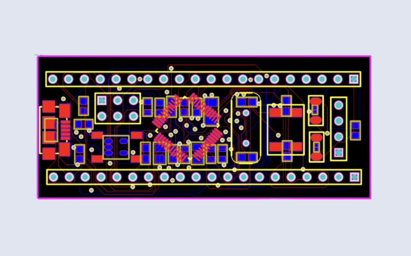
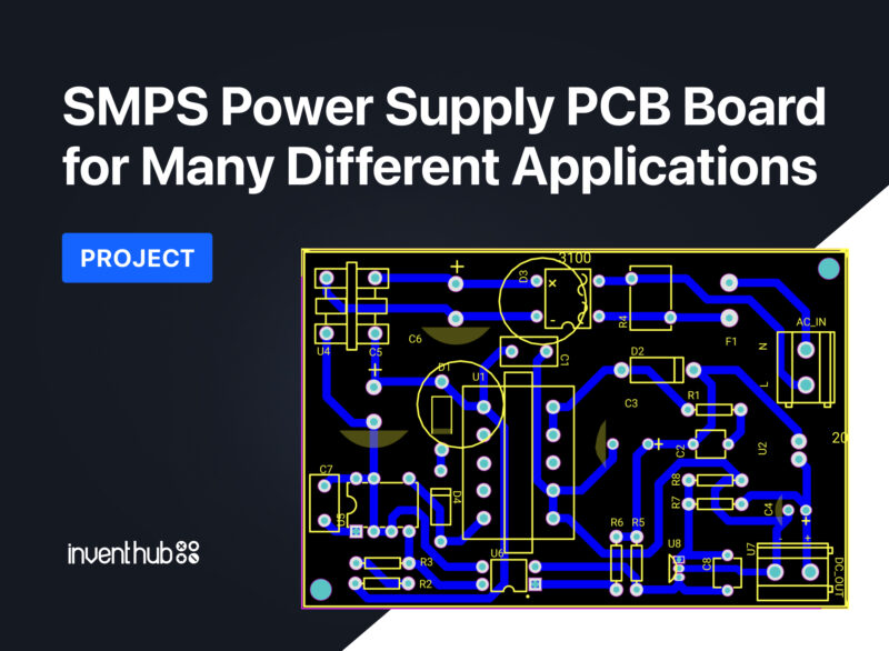
PCB Design Board:
After the implementation of the schematic, I have converted my design to a PCB file so that I can design my board and can view it in 3D view. For the fabrication of my board, I have uploaded my PCB and all design files on Inventhub for the manufacturers. They only need to download the ZIP file format and they can fabricate my PCB board without making any error in the design.


BOM file:
I have created a BOM file for those who want to work on my design they want to know about each component and for the component providers to deliver the components. It contains the detail of each component used like dimensions, manufacturer, quantity symbol, and footprint library reference.

Applications of the Design Board:
This SMPS PCB board can be used in different applications like;
- Electronic gadgets like mobiles, laptops, chargers, etc.
- Machines in Industry
- Vehicles like electric cars and in railway stations
- Safety and security; to protect the devices
- Home appliances
Project History:
I have created multiple revisions in my project and I have uploaded them all online on Inventhub to keep them as my backup design. If I want to use my previous design as my current design I do not need to Undo my current design I can easily use my specific revision of the design by going into my project revisions. I can download and can reuse it as my final design.

Altium PCB Design: